Radiation Pattern - Part 1 | Part 2
The speed of electromagnetic wave is the same as speed of light, light is also an electromagnetic wave. In empty space, the speed is 299, 799, 077 meters per second. The Physical Length of a frequency λ = v/f, where 'v' is the Velocity, 'λ' is the wave length and 'f' is the frequency. For example, if f = 145.000 MHz., then the Physical Length is (300 / 145) = 2.06896 meters. Because of the velocity factor K of the conductor, the Physical Electrical Length is less than the Free Space Length. Normally, for practical purposes, K is taken as 0.95. To obtain Electrical length for practical applications, K is used as a multiplier, it will change as (300 x 0.95) / 145 = 1.96551 m. For a half - wave dipole, the equation is, (150 x 0.95 ) / 145 and it is 0.98275 m (98.275 cm). The Fig. E gives details of the (λ / 8)th combinations in vertical class. If the diameter of this circle is 1.96551 m, it comes as 1.96551 / 8 and it is 0.245688 m (24.568 cm). This value is equal to 45° wave. It is the (1/8)th length of 145 MHz. For getting the 5/8th Antenna, radiator length should be 24.568 cm x 5 and it is equal to 1.2284 m. Refer table 1 for getting λ/8th combinations at 145 MHz.

In Amateur Radio Terminology, the (5/8)th Antenna is known as 225° wave Antenna. In Fig. E, you can see the cycle starting from 0 to 360 degrees in clockwise direction and the position of 225°. Therefore the 1/2 λ is known as 180° wave and (1/4)λ is known as 90° wave.
In some commercial antennas, the real length of the radiator is less than what they have specified. For Example, if the (5/8)th Antenna (225° wave) on 145 MHz. is 1.22 m long, the tolerance of the length is + 1 cm, which is acceptable. If the length is 98.27 cm long, then it is a (4/8)th antenna, the radiation (gain) in such antenna is lower than 5/8th antenna.


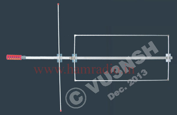
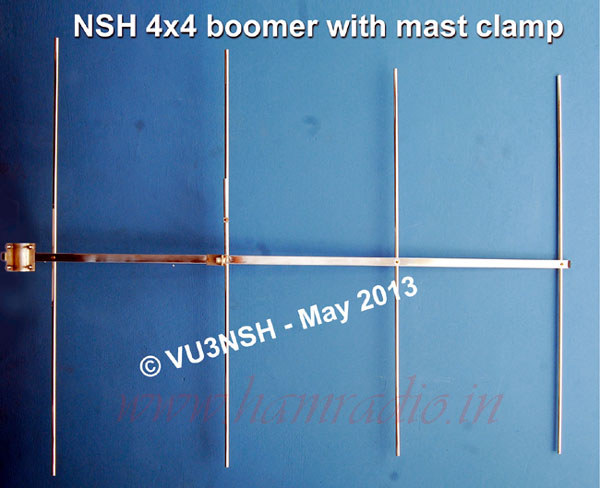
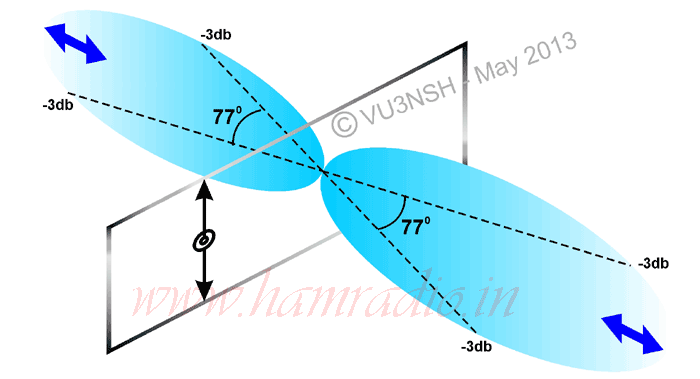
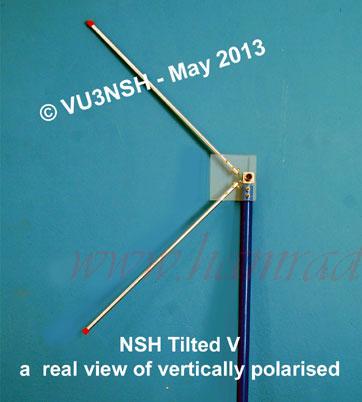
In Figure 1, 2, 3 and 4, you can see the radiation angles of vertical antennas and some analogies (Fig.2). Generally all vertical antennas radiate in 360°, but the question is, in which angle the radiation is more in horizontal plane. It will produce useful angle of radiations for working long distances (refer Fig. 3 and Fig. 4). The 360° omni directional radiations from vertical antennas are not equal (Fig. 4). The vertical antennas has its own behaviors in gain, radiation angle, effective aperture etc. But you have to choose for the best antennas for your own purpose. Whether we buy or build our antennas, we soon find out that is no one 'best' design for all purposes - ARRL - 1978, Page 623 - Hi.


Testing of a new antenna with repeaters depends upon the conditions of the repeater performance, propagation conditions, reporting stations' capabilities of discriminating the signals with his set-up. "Some repeaters are known as 'alligators', all mouth, no ears, we need a good loud signal coming and going" - Mc Coy on ANTENNAS, Page 98 - CQ - Hi.
In most conditions, the 'user problems', misunderstood function of SWR, matching, propagation, doubtful coaxial or cable into which moisture has seeped (mismatch or high loss), 'free space' conditions, Rx-Tx antenna degrees of accuracy, distance in between stations and elevation, measuring equipment, reflection from other conductors or from large building, signal reports from other stations with 'S' meters (S meters are not universally calibrated - Hi!), and so many variable factors involved. The only reliable test can be done by accurate measuring equipment. Using different types of vertical antennas in your QTH with different heights and place, to confirm, which is suitable for your local work (simplex) and for DXing with minimum TX power.
I hope this text, all figures and diagrams are sufficient for some basic knowledge about antennas. I thank OM VU2DX for the proof reading and Rejeesh (SWL) for making the illustrations for my article.


