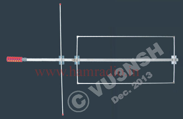
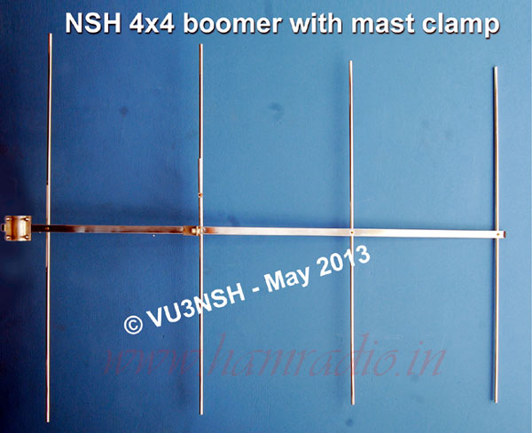
It is a high gain simple beam antenna for 2 meter frequency. It is just a 4 element on 4 feet boom with a gain of 8 dB and having a low SWR of 1.2 : 1 on the operating frequency 144 to 146 MHz. NSH 4x4 Boomer was simulated due to the need of a beam antenna with minimum elements, minimum boom length and maximum forward gain. Moreover the SWR must be within the limit. The homebrew cost also should be low. This antenna is very easy to carry anywhere for portable operations like disaster management, field day etc. Due to 4 feet boom it can be mounted within the restricted spaces.

Specification
- Gain :- 8.2 dB Max
- F / B Ratio :- 18 dB typical
- Bandwidth :- 1.2 : 1 for 2 MHz
- Power :- Upto 200 W
- Beam width :- 24 degree typical
- Boom Size :- 225 elec. degrees
In this design all elements are equally spaced with 0.2066 lambda. With a single gama match, like a normal beam, it can be tuned for low SWR level in the operating frequency. I constructed this optimised model with 3/4 x 3/4, with 1 mm thick square boom and 3/8 th 1.5 mm thick aluminium tubes as elements. All of these elements are mirror polished for getting more gain and for reducing the skin effect in VHF work.
These elements are fixed in typical methods which I had used in my 7 element design long back (in 1994-95 experiments) (Refer 7 Element VHF High Gainer and visit www.youtube.com/watch?v=wH3y7ztjPOg), i.e. 'through the boom method' so that no need of any element clamps for fixing the elements on the Boom. The middle of all elements are tapped for fixing the screws so that, one screw is enough to fix the element through the boom. There is no need of any nuts for this purpose.
The first on air test from my home was at a low height of 3 feet to access local stations. It was fine and I got stations around 15 kms. as 5 9. Then one day VU3SYG, Saleem came and he was interested to carry the experiment from his QTH at Palakkad. He connected with his handheld and done a fully portable operation at his first floor by holding the antenna at one hand and he got the VU2HEN repeater from Idukki as 5 7 signals bothways.
The total size of the boom is 0.682 λ (1.22 meters / 4 feet). Physical length of your operating frequency (λ = 300 × 0.95 / f) × 0.2066 = The spacing of each elements (for 145 MHz, λ = 1.967 m), Ref = 0.525 × λ, DE = 0.5054 × λ, Dir 1 = 0.4745 × λ, Dir 2 = 0.4715 × λ. These element lengths are including the boom size of 19.4 mm. So there is no need of adding the boom size with the calculated result.
Gamma section needs protection from moisture, rain water etc. After tuning with the SWR meter, wrap teflon tape on total gamma section to prevent from WX problems. Remember that the gamma tube should be upward and the coaxial cable from gamma section parallel with boom and take it down after the reflector like NSH 7 element beam (Refer the link 7 Element VHF High Gainer).


