Radiation Pattern Part 1 | Part 2

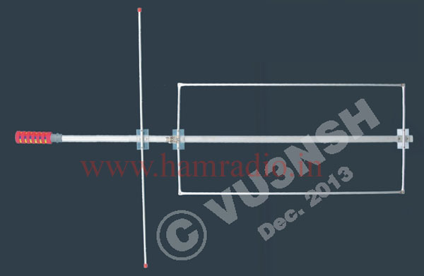
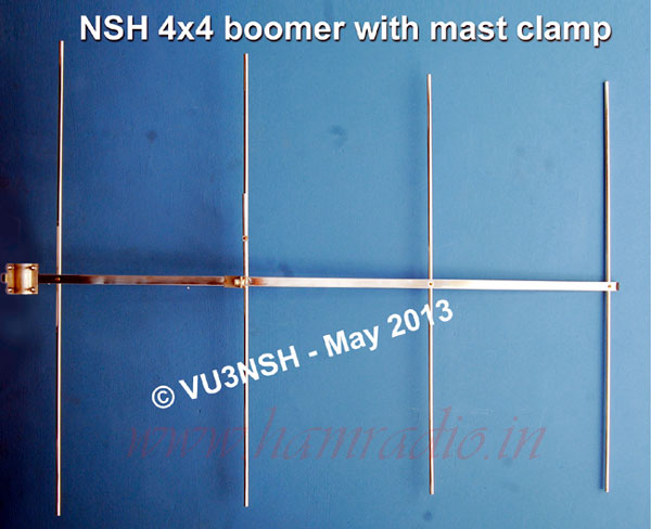
An antenna will always have some "Ohmic Resistance", which is the first element. In ohmic resistance, power is dissipated as heat and is lost, like in a resistor. The radiation resistance is the second element, which determines what portion of TX Power is coupled to space and radiated. The third element is called "reactance", in which there are two types (a) capacitive [notation (-j)] , (b) inductive [notation (+j)] (See Figure A). A perfect antenna is a 50 Ω resistive load to the transmitter, which gives an excellent performance. Radiation resistance is defined as the ratio of power radiated by the antenna to the square of the current at the feed point. Radiation resistance is that value of resistance, if replaced, the radiation mechanism of antenna would dissipate exactly the same amount of power that the antenna radiated. In Fig. A-1, typical radiation patterns for a 2-element beam are shown, and its horizontal field over 360° and its vertical angle of radiation. It is necessary to be able to physically rotate antennas in order to get maximum power in a required direction. In many amateur systems the requirement is for a highly directive pattern to achieve increased "gain and interference reduction". However, for such systems like repeaters and mobile communication, it is often necessary to radiate energy in an omni-directional pattern, in order to provide a broadcast type of coverage.


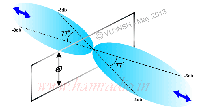
With amateur antennas, which normally have radiation patterns of a simple shape, the important characteristics of the patterns can be specified by the beam width and side lobe level in the two principal planes, usually taken as the V (vertical) plane and the H (Horizontal) plane. The beam width in a principal plane of the radiation pattern is defined by the pattern’s angular width at a level which is 3dB down from the beam maximum. Refer Fig. A2. This is also known as the "half-power beam width". Side lobes (radiation in any direction other than that required) and the front to back ratio (F/B ratio) with directional beam antennas (the ratio of the energy radiated in the required direction to that radiated in the diametrically opposite direction - 180°, Ref. Fig. A2) are both expressed as the number of decibels (dB) down with respect to the maximum radiation of the main beam. The directional antennas have directivity gain. This useful degree of gain (Fig. A3) is very much useful for DXing with minimum TX power.


The gain of an antenna is usually expressed as a power ratio, either as a multiple of so many "times", or in dB units. λ / 2 dipole ( a λ / 2 wave long antenna is called Hertz Antenna, the λ / 4 is called Marconi Antenna) is the hypothetical isotropic radiator is 1.64 times or 2.15 dB power gain, it is generally accepted as a basis of comparison. For example, a 13dB antenna’s multiplier is 19.95 times say 20, in such antenna, the input power of 50W, the effective radiated power should be 20 x 50 W = 1000 W ERP !!!. In the case of a λ / 2 dipole with 50W input, it is 1.64 x 50 = 82 W !! In two types of vertical antennas with same height and same TX power, illustrated in Fig. A5, low gain antenna works as an alligator with high power TX, big mouth, no ears !!!. High gain antennas are needed for good communication.


Consider an antenna after proper matching which shows a VSWR of 2:1 (Sometimes written as 2/1 or, 2 to 1). Then, in 50 Ω transceiver, the load (antenna) impedance on that frequency is 100 Ω or 25 Ω; or if the antenna shows 3:1 VSWR, i.e., the impedance are 150 Ω or 16.5 Ω. This is a mismatch level. The 50 Ω impedance are convenient and easy to use, input and output of a device matched to 50 Ω allows an easy transfer of other replacement units. The reflection product is the power "bounced back" from the load due to mismatched impedances at the load (antenna) or from the feeder. If the VSWR of a system shows 3:1, then the matching efficiency is 75%, so the loss is 25%, i.e., for a 100W, TX power fed to such a system, 25W is the reflected power. For 1000W, the reflected power from the system is 250 W!. The cable will melt !!! .......
The PA stage of your TX will be damaged. For this kind of system, if it receives a signal, the above mentioned loss is also applicable. So a weak signal can’t be received properly reciprocal characteristic of the antenna). In the case of 50 Ω TX system a 75 Ω cable, itself will have a VSWR of 1.5:1. In this 75 Ω cable, if a 3:1 load is connected, then the total VSWR is 4.5:1 and also cable’s own loss as per manufacture’s data according to the frequency / length. The total loss in the system will be including mismatch cable, antenna mismatch, cable attenuation and inferior connector loss.
In some conditions, highly mismatched cables show low VSWR. Due to reflected power from the load to the VSWR meter, absorbed (self loss) or attenuated by the cable itself. It can be identified by testing the system by the next TX high power. So this will show the reflective level. This means testing with a low power cannot be accurate. Test should be done with different TX power levels. The TX power from the rig to the antenna should be efficiently transferred as much as possible by the feed line without radiating. If it radiates, it is no longer a feeder line (feeder cable), it becomes a part of the antenna. Due to feed - line radiation, any flow of current on the outside of coax feed line is known as "parallel standing waves". This current can also flow into VSWR meter, resulting in false readings combined with the normal VSWR readings. Placing the VSWR meter at different placesin the feed lines, you can check these problems of cable radiations or by using a field strength meter.
A cable can be tested for confirming its characteristics, by connecting a 50 Ω dummy load instead of antenna, and a VSWR / power meter in between TX and dummy load. If it shows 1:1 VSWR, then the cable is OK, if it sows 1.5:1, then the cable is a 75 Ω type. The loss of such cable is 4%. Cable attenuation at operating frequency / length is also added with the 4% loss. It is essential to check whether the full amount of power reaches the antenna from the transmitter and that equally full level of received signal is being transferred from antenna to receiver. Cable into which moisture has seeped in, the outer conductor becomes tarnished due to oxide formation and each lead acts as individual conductor. This will change its own impedance level. The physical length of an antenna should be checked for resonance, it means they must be electrically tuned to the operating frequency. Radio frequency current travels slower in metal conductors than in a free space. Its electrical length is less than the length in free space.

The feeder cable length is critical. If a shorted line is less than a quarter-wave long, it will have "inductive" reactance. If it is beyond that, it is a "capacitive". So odd multiple of a quarter wave length of the operating frequency is the matched line. See Table 1. If the reflected waves arrive from ground or from some point, the result could be a strong signal (due to the wave arriving in phase); if a weak signals received, it is due to the waves arriving out of phase (because in phase, signal add-up and out-of -phase signals cancel each other or distorted by delayed reflected signal). In practice, VHF / UHF wave propagation is more seriously affected by shadowing due to high buildings, heavily wooded ground, hills, or by diffraction and absorption losses. To avoid this kind of problems, while using a beam antenna system, the beam direction can be changed. See Fig. A4 and A6.
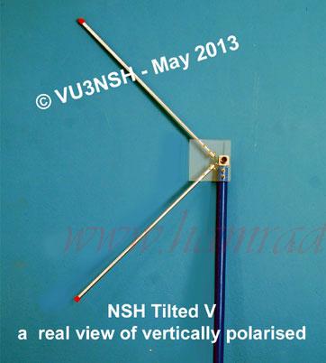
Toroidal radiation pattern (Omni) is used for radio communication, radio navigation and radio broadcasting. Pencil beam radiation pattern is mostly used for radar, long range communications, etc. Fan beam patterns are also used for radar and communication radio systems. The cosecant beam patterns are preferable in air-borne ground surveillance and ground-based air surveillance radars. It is established that an antenna system according to the use should be chosen.
I thank Dr. T.K.Mani VU2ITI (Principal, College of Engineering, Cherthala), VU2DX, R.S.RAMA RAO VU2RID (IBS) for the proof reading and advice, and SWL Rejeesh for making the illustration and Sajeesh for the data processing for my article.
Reference :
- Micro wave Circuits and Antennas - MIR - Russia, ISBN-5-03-001411-X1990-By D.M.SAZNOV
- ARRL Antenna Hand Book - 18th Edition - US, ISBN-0-87259-613-3
- VHF UHF Manual - RSGB - UK, ISBN-0-900612-63-0-1997
- Radio Measurements - MIR - Russia, 1978 - By F.KUSHNIR
- Practical Wireless - August 1980 - UK, Power Gain from TX Aerials - By G2BCX
- How to Make Walkie Talkies - BP 43 - BABANI - UK
- All About VHF Amateur Radio - W6 SAI - RAC - US, ISBN-0-8230-8705-0
- Lew Mc Coy on Antennas - CQ - US, ISBN-0-943016-08-8
- Two Meter Antenna Hand Book - FC Judd - G2BCX - UK, ISBN-0-408-00402-9
- 73 Amateur Radio Today - 1995 - US, Above and Beyond - By WB6IGP
- Out of Thin Air - PW - UK, IPC - Magazines Ltd.
- Vertical Antenna Classics - ARRL - US, ISBN-0-87259-521-8
- Electricity and Magnetism - MIR - Russia, 1986 - By A.N.MATVEEV
- ARRL Hand Book - 1968, 1978, 1989 - ARRL - US
- Networks Lines and Fields - G.S.Bijoor - Hi-Tech Series - Subghas Publications, BLR2
